To start with this try out, you should unpack
TryOut01.tar.gz to
your working directory, and compile/link it as it is.
$ cd TryOut01
$ make
If you had already compiled/linked A01app for Exercise 0, you might have problem on dependency files. "make clean" does not work in this case. If you have this problem, delete all dependency files related to A01app.
$ rm -r $G4WORKDIR/tmp/Linux-g++/A01app/Once you succeed to compile/link, just try it to see how it runs.
$ $G4WORKDIR/bin/Linux-g++/A01appAfter some initialization, a prompt Idle> should appear. Then, adopt a UI command for executing a provided macro file.
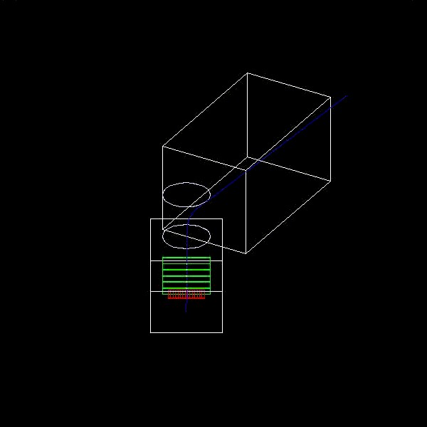
Idle> /control/execute opengl.macYou should get this drawing.
As you see, compared to Exercise 0, you don't have any detectors in the second lever arm. In addition, although the primary paricle is positively charged (charged giantino, artificial particle defined in Geant4 which has popsitive charge but does not involve to any physics interaction except transportation in magnetic field), it went strait. Note that a trajectory drawn in blue is positively charged particle. This is because this sample code does not have any magnetic field. In this exercise, you are supposed to define a magnetic field and put detectors into the second lever arm.
| A part of A01MagneticField.cc |
void A01MagneticField::GetFieldValue(const double Point[3],double *Bfield) const
{
  Bfield[0] = 0.;
  Bfield[2] = 0.;
  if(abs(Point[1])<ymax && (sqr(Point[0])+sqr(Point[2]))<rmax_sq)
  { Bfield[1] = By; }
  else
  { Bfield[1] = 0.; }
}
|
Now, you have to attach this field class to the G4FieldManager. To do this, you have to modify A01DetectorConstruction.cc.
Given a pointer of A01MagneticField class object has already defined as a data member of A01DetectorConstruction class, what you have to do is
| A part of A01DetectorConstruction.cc |
#include "A01DetectorConstMessenger.hh"
#include "A01Hodoscope.hh"
#include "A01DriftChamber.hh"

#include "G4FieldManager.hh"
#include "G4TransportationManager.hh"
#include "A01MagneticField.hh"

A01DetectorConstruction::A01DetectorConstruction()
 : air(0), argonGas(0), scintillator(0),
   worldVisAtt(0), magneticVisAtt(0),
   armVisAtt(0), hodoscopeVisAtt(0), chamberVisAtt(0),
   wirePlaneVisAtt(0), EMcalorimeterVisAtt(0), cellVisAtt(0),
   armAngle(30.*deg), secondArmPhys(0)
{
  messenger = new A01DetectorConstMessenger(this);
  magneticField = new A01MagneticField();
  armRotation = new G4RotationMatrix();
  armRotation->rotateY(armAngle);
}

A01DetectorConstruction::~A01DetectorConstruction()
{
  delete magneticField;
  delete armRotation;
  delete messenger;

  DestroyMaterials();

  delete worldVisAtt;
  delete magneticVisAtt;
  delete armVisAtt;
  delete hodoscopeVisAtt;
  delete chamberVisAtt;
  delete wirePlaneVisAtt;
}

G4VPhysicalVolume* A01DetectorConstruction::Construct()
{
  // All managed (deleted) by SDManager
  G4VSensitiveDetector* hodoscope1;
  G4VSensitiveDetector* chamber1;

  ConstructMaterials();

  // Magnetic field ----------------------------------------------------------
  static G4bool fieldIsInitialized = false;
  if(!fieldIsInitialized)
  {
    G4FieldManager* fieldMgr
      = G4TransportationManager::GetTransportationManager()->GetFieldManager();
    fieldMgr->SetDetectorField(magneticField);
    fieldMgr->CreateChordFinder(magneticField);
    fieldIsInitialized = true;
  }

             ..... snipped .....
|
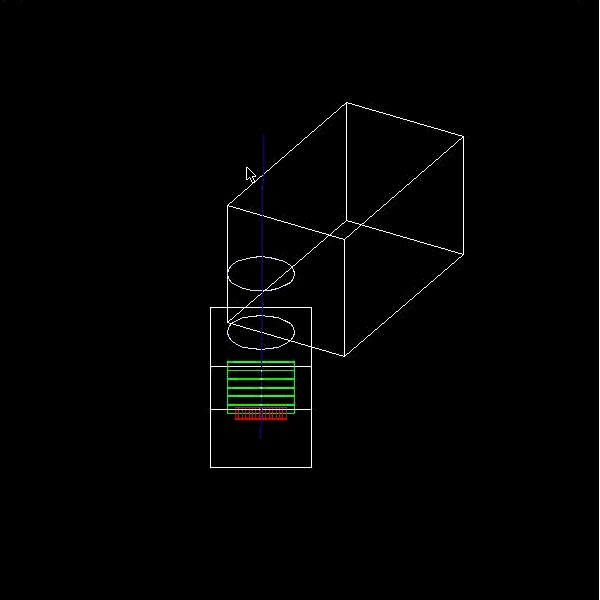
Once you finish edditting, comple/link the code once again and see how it runs with the same macro file. Have you got a curved trajectory?
| A part of A01DetectorConstruction.hh |
class A01DetectorConstruction : public G4VUserDetectorConstruction
{
  public:
    A01DetectorConstruction();
    virtual ~A01DetectorConstruction();

  public:
    virtual G4VPhysicalVolume* Construct();
    void SetArmAngle(G4double val);
    inline G4double GetArmAngle() { return armAngle; }

  private:
    void ConstructMaterials();
    void DestroyMaterials();
    void DumpGeometricalTree(G4VPhysicalVolume* aVolume,G4int depth=0);

  private:
    A01DetectorConstMessenger* messenger;
    A01MagneticField* magneticField;

    G4Material* air;
    G4Material* argonGas;
    G4Material* scintillator;
    G4Material* CsI;
    G4Material* lead;

      ..... snipped .....
|
| A part of A01DetectorConstruction.cc |
A01DetectorConstruction::A01DetectorConstruction()
 : air(0), argonGas(0), scintillator(0),
   CsI(0), lead(0),
   worldVisAtt(0), magneticVisAtt(0),
   armVisAtt(0), hodoscopeVisAtt(0), chamberVisAtt(0),
   wirePlaneVisAtt(0), EMcalorimeterVisAtt(0), cellVisAtt(0),
   armAngle(30.*deg), secondArmPhys(0)
{
  messenger = new A01DetectorConstMessenger(this);
  magneticField = new A01MagneticField();
  armRotation = new G4RotationMatrix();
  armRotation->rotateY(armAngle);
}
|
Lead can be defined as a simple material. Following are the quantities for defining lead.
CsI should be defined as a mixture made of I and Cs. Following are the quantities for defining lead.
| A part of A01DetectorConstruction.cc |
void A01DetectorConstruction::ConstructMaterials()
{
  G4double a;
  G4double z;
  G4double density;
  G4double weightRatio;
  G4String name;
  G4String symbol;
  G4int nElem;

  // Argon gas
  a = 39.95*g/mole;
  density = 1.782e-03*g/cm3;
  argonGas = new G4Material(name="ArgonGas", z=18., a, density);

  // elements for mixtures and compounds
  a = 1.01*g/mole;
  G4Element* elH = new G4Element(name="Hydrogen", symbol="H", z=1., a);
  a = 12.01*g/mole;
  G4Element* elC = new G4Element(name="Carbon", symbol="C", z=6., a);
  a = 14.01*g/mole;
  G4Element* elN = new G4Element(name="Nitrogen", symbol="N", z=7., a);
  a = 16.00*g/mole;
  G4Element* elO = new G4Element(name="Oxigen", symbol="O", z=8., a);

  // Air
  density = 1.29*mg/cm3;
  air = new G4Material(name="Air", density, nElem=2);
  air->AddElement(elN, weightRatio=.7);
  air->AddElement(elO, weightRatio=.3);

  // Scintillator
  density = 1.032*g/cm3;
  scintillator = new G4Material(name="Scintillator", density, nElem=2);
  scintillator->AddElement(elC, 9);
  scintillator->AddElement(elH, 10);

  // Lead
  a = 207.19*g/mole;
  density = 11.35*g/cm3;
  lead = new G4Material(name="Lead", z=82., a, density);

  // CsI
  a = 126.9*g/mole;
  G4Element* elI = new G4Element(name="Iodine", symbol="I", z=53., a);
  a = 132.9*g/mole;
  G4Element* elCs= new G4Element(name="Cesium", symbol="Cs", z=55., a);
  density = 4.51*g/cm3;
  CsI = new G4Material(name="CsI", density, nElem=2);
  CsI->AddElement(elI, weightRatio=.5);
  CsI->AddElement(elCs,weightRatio=.5);

  G4cout << G4endl << "The materials defined are : " << G4endl << G4endl;
  G4cout << *(G4Material::GetMaterialTable()) << G4endl;
}
|
After implementing above, try your code. At the beginning of the program execution, you have a list of defined materials. You should now have two of new materials, lead and CsI.
| A part of output |
The materials defined are : ***** Table : Nb of materials = 5 ***** Material: ArgonGas density: 1.782 kg/m3 temperature: 273.15 K pressure: 1.00 atm RadLength: 109.708 m ---> Element: ArgonGas Z = 18.0 N = 40.0 A = 39.95 g/mole fractionMass: 100.00 % Abundance 100.00 % Material: Air density: 1.290 kg/m3 temperature: 273.15 K pressure: 1.00 atm RadLength: 285.161 m ---> Element: Nitrogen N Z = 7.0 N = 14.0 A = 14.01 g/mole fractionMass: 70.00 % Abundance 72.71 % ---> Element: Oxigen O Z = 8.0 N = 16.0 A = 16.00 g/mole fractionMass: 30.00 % Abundance 27.29 % Material: Scintillator density: 1.032 g/cm3 temperature: 273.15 K pressure: 1.00 atm RadLength: 42.549 cm ---> Element: Carbon C Z = 6.0 N = 12.0 A = 12.01 g/mole fractionMass: 91.45 % Abundance 47.37 % ---> Element: Hydrogen H Z = 1.0 N = 1.0 A = 1.01 g/mole fractionMass: 8.55 % Abundance 52.63 % Material: Lead density: 11.350 g/cm3 temperature: 273.15 K pressure: 1.00 atm RadLength: 5.612 mm ---> Element: Lead Z = 82.0 N = 207.2 A = 207.19 g/mole fractionMass: 100.00 % Abundance 100.00 % Material: CsI density: 4.510 g/cm3 temperature: 273.15 K pressure: 1.00 atm RadLength: 1.861 cm ---> Element: Iodine I Z = 53.0 N = 126.9 A = 126.90 g/mole fractionMass: 50.00 % Abundance 51.15 % ---> Element: Cesium Cs Z = 55.0 N = 132.9 A = 132.90 g/mole fractionMass: 50.00 % Abundance 48.85 % |
Important note
Let's start with hodoscope. Each hodoscope finger is a box made of scintillator. The size of a finger is 10.*cm, 40.*cm, 1.*cm. To define a G4Box, you should note that you have to give half length for its size. Then G4LogicalVolume must be instantiated. Then, you have to place fingers. There should be 25 fingers along the X axis. Y and Z position of them are zero.
| A part of A01DetectorConstruction.cc |
G4VPhysicalVolume* A01DetectorConstruction::Construct()
{

    ..... snipped .....

  // "virtual" wire plane
  G4VSolid* wirePlane1Solid = new G4Box("wirePlane1Box",1.*m,30.*cm,0.1*mm);
  G4LogicalVolume* wirePlane1Logical
    = new G4LogicalVolume(wirePlane1Solid,argonGas,"wirePlane1Logical",0,0,0);
  new G4PVPlacement(0,G4ThreeVector(0.,0.,0.),wirePlane1Logical,
                    "wirePlane1Physical",chamber1Logical,0,0);

  // hodoscopes in second arm
  G4VSolid* hodoscope2Solid = new G4Box("hodoscope2Box",5.*cm,20.*cm,0.5*cm);
  G4LogicalVolume* hodoscope2Logical
    = new G4LogicalVolume(hodoscope2Solid,scintillator,"hodoscope2Logical",0,0,0);
  for(int i2=0;i2<25;i2++)
  {
    G4double x2 = (i2-12)*10.*cm;
    new G4PVPlacement(0,G4ThreeVector(x2,0.,0.),hodoscope2Logical,
                      "hodoscope2Physical",secondArmLogical,0,i2);
  }

  // sensitive detectors -----------------------------------------------------
  G4SDManager* SDman = G4SDManager::GetSDMpointer();
  G4String SDname;

    ..... snipped .....
|
In addition, set the visualization attribute (actually the color) to the logical volume of the hodoscope finger. Given hodoscope fingers in the first lever arm already have visualization attribute, let's re-use it.
| A part of A01DetectorConstruction.cc |
..... snipped ..... // visualization attributes ------------------------------------------------ worldVisAtt = new G4VisAttributes(G4Colour(1.0,1.0,1.0)); worldVisAtt->SetVisibility(false); worldLogical->SetVisAttributes(worldVisAtt); magneticVisAtt = new G4VisAttributes(G4Colour(0.9,0.9,0.9)); // LightGray magneticVisAtt->SetForceWireframe(true); magneticLogical->SetVisAttributes(magneticVisAtt); armVisAtt = new G4VisAttributes(G4Colour(1.0,1.0,1.0)); armVisAtt->SetVisibility(true); firstArmLogical->SetVisAttributes(armVisAtt); secondArmLogical->SetVisAttributes(armVisAtt); hodoscopeVisAtt = new G4VisAttributes(G4Colour(0.8888,0.0,0.0)); hodoscopeVisAtt->SetForceWireframe(true); hodoscope1Logical->SetVisAttributes(hodoscopeVisAtt); chamberVisAtt = new G4VisAttributes(G4Colour(0.0,1.0,0.0)); chamberVisAtt->SetForceWireframe(true); chamber1Logical->SetVisAttributes(chamberVisAtt); wirePlaneVisAtt = new G4VisAttributes(G4Colour(0.0,0.8888,0.0)); wirePlaneVisAtt->SetVisibility(false); wirePlane1Logical->SetVisAttributes(wirePlaneVisAtt); hodoscope2Logical->SetVisAttributes(hodoscopeVisAtt); // return the world physical volume ---------------------------------------- G4cout << G4endl << "The geometrical tree defined are : " << G4endl << G4endl; DumpGeometricalTree(worldPhysical); return worldPhysical; } |
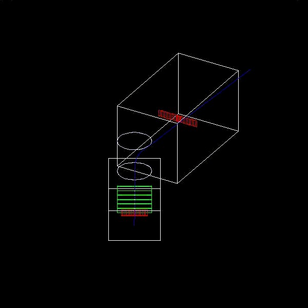
Now, Comple/link the code once again and see how it runs with the same macro file. Have you seen hodoscope fingers in the second lever arm?
In addition, for the sake of getting a precise position of a hit along the track, let's define an artificial wire plane to each of drift chambers. Wire plane should be made of argon gas as well, same hight and width as the chamber itself, and the thickness should be 0.2*mm. It should be placed at the center of each drift chamber. You don't have to place this wire plane five times, but just put it once to the logical volume of drift chamber.
Visualization attribute for drift chamber and wire plane should be re-used from ones for the first lever arm.
| A part of A01DetectorConstruction.cc |
   ..... snipped .....

  // hodoscopes in second arm
  G4VSolid* hodoscope2Solid = new G4Box("hodoscope2Box",5.*cm,20.*cm,0.5*cm);
  G4LogicalVolume* hodoscope2Logical
    = new G4LogicalVolume(hodoscope2Solid,scintillator,"hodoscope2Logical",0,0,0);
  for(int i2=0;i2<25;i2++)
  {
    G4double x2 = (i2-12)*10.*cm;
    new G4PVPlacement(0,G4ThreeVector(x2,0.,0.),hodoscope2Logical,
                      "hodoscope2Physical",secondArmLogical,0,i2);
  }

  // drift chambers in second arm
  G4VSolid* chamber2Solid = new G4Box("chamber2Box",1.5*m,30.*cm,1.*cm);
  G4LogicalVolume* chamber2Logical
    = new G4LogicalVolume(chamber2Solid,argonGas,"chamber2Logical",0,0,0);
  for(int j2=0;j2<5;j2++)
  {
    G4double z2 = (j2-2)*0.5*m - 1.5*m;
    new G4PVPlacement(0,G4ThreeVector(0.,0.,z2),chamber2Logical,
                      "chamber2Physical",secondArmLogical,0,j2);
  }

  // "virtual" wire plane
  G4VSolid* wirePlane2Solid = new G4Box("wirePlane2Box",1.5*m,30.*cm,0.1*mm);
  G4LogicalVolume* wirePlane2Logical
    = new G4LogicalVolume(wirePlane2Solid,argonGas,"wirePlane2Logical",0,0,0);
  new G4PVPlacement(0,G4ThreeVector(0.,0.,0.),wirePlane2Logical,
                    "wirePlane2Physical",chamber2Logical,0,0);

  // sensitive detectors -----------------------------------------------------
  G4SDManager* SDman = G4SDManager::GetSDMpointer();
  G4String SDname;

  hodoscope1 = new A01Hodoscope(SDname="/hodoscope1");
  SDman->AddNewDetector(hodoscope1);
  hodoscope1Logical->SetSensitiveDetector(hodoscope1);

  chamber1 = new A01DriftChamber(SDname="/chamber1");
  SDman->AddNewDetector(chamber1);
  wirePlane1Logical->SetSensitiveDetector(chamber1);

  // visualization attributes ------------------------------------------------

  worldVisAtt = new G4VisAttributes(G4Colour(1.0,1.0,1.0));
  worldVisAtt->SetVisibility(false);
  worldLogical->SetVisAttributes(worldVisAtt);

  magneticVisAtt = new G4VisAttributes(G4Colour(0.9,0.9,0.9));   // LightGray
  magneticVisAtt->SetForceWireframe(true);
  magneticLogical->SetVisAttributes(magneticVisAtt);

  armVisAtt = new G4VisAttributes(G4Colour(1.0,1.0,1.0));
  armVisAtt->SetVisibility(true);
  firstArmLogical->SetVisAttributes(armVisAtt);
  secondArmLogical->SetVisAttributes(armVisAtt);

  hodoscopeVisAtt = new G4VisAttributes(G4Colour(0.8888,0.0,0.0));
  hodoscopeVisAtt->SetForceWireframe(true);
  hodoscope1Logical->SetVisAttributes(hodoscopeVisAtt);

  chamberVisAtt = new G4VisAttributes(G4Colour(0.0,1.0,0.0));
  chamberVisAtt->SetForceWireframe(true);
  chamber1Logical->SetVisAttributes(chamberVisAtt);

  wirePlaneVisAtt = new G4VisAttributes(G4Colour(0.0,0.8888,0.0));
  wirePlaneVisAtt->SetVisibility(false);
  wirePlane1Logical->SetVisAttributes(wirePlaneVisAtt);

  hodoscope2Logical->SetVisAttributes(hodoscopeVisAtt);
  chamber2Logical->SetVisAttributes(chamberVisAtt);
  wirePlane2Logical->SetVisAttributes(wirePlaneVisAtt);

  // return the world physical volume ----------------------------------------

  G4cout << G4endl << "The geometrical tree defined are : " << G4endl << G4endl;
  DumpGeometricalTree(worldPhysical);

  return worldPhysical;
}
|
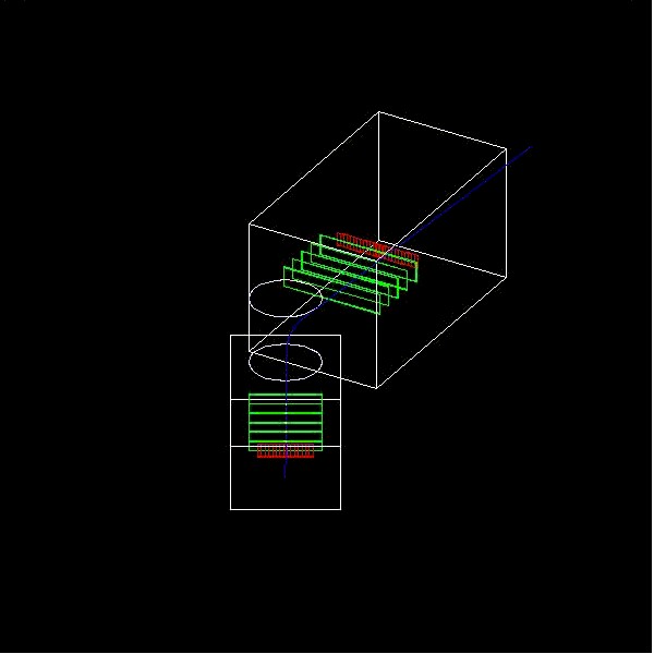
Now, Comple/link the code once again and see how it runs with the same macro file. Have you seen drift chambers in the second lever arm?
This time, you have to define visualization attributes for EM calorimeter and crystal cell. Let's paint them orane and yellow respectively, and force them drawn in wireframe. Don't forget to include G4PVParameterised.hh and A01CellParameterisation.hh.
| A part of A01DetectorConstruction.cc |
#include "G4PVParameterised.hh"
#include "A01CellParameterisation.hh"

    ..... snipped .....

  // "virtual" wire plane
  G4VSolid* wirePlane2Solid = new G4Box("wirePlane2Box",1.5*m,30.*cm,0.1*mm);
  G4LogicalVolume* wirePlane2Logical
    = new G4LogicalVolume(wirePlane2Solid,argonGas,"wirePlane2Logical",0,0,0);
  new G4PVPlacement(0,G4ThreeVector(0.,0.,0.),wirePlane2Logical,
                    "wirePlane2Physical",chamber2Logical,0,0);

  // CsI calorimeter
  G4VSolid* EMcalorimeterSolid = new G4Box("EMcalorimeterBox",1.5*m,30.*cm,15.*cm);
  G4LogicalVolume* EMcalorimeterLogical
    = new G4LogicalVolume(EMcalorimeterSolid,CsI,"EMcalorimeterLogical",0,0,0);
  new G4PVPlacement(0,G4ThreeVector(0.,0.,2.*m),EMcalorimeterLogical,
                    "EMcalorimeterPhysical",secondArmLogical,0,0);

  // EMcalorimeter cells
  G4VSolid* cellSolid = new G4Box("cellBox",7.5*cm,7.5*cm,15.*cm);
  G4LogicalVolume* cellLogical
    = new G4LogicalVolume(cellSolid,CsI,"cellLogical",0,0,0);
  G4VPVParameterisation* cellParam = new A01CellParameterisation();
  new G4PVParameterised("cellPhysical",cellLogical,EMcalorimeterLogical,
                         kXAxis,80,cellParam);

    ..... snipped .....

  wirePlaneVisAtt = new G4VisAttributes(G4Colour(0.0,0.8888,0.0));
  wirePlaneVisAtt->SetVisibility(false);
  wirePlane1Logical->SetVisAttributes(wirePlaneVisAtt);

  hodoscope2Logical->SetVisAttributes(hodoscopeVisAtt);
  chamber2Logical->SetVisAttributes(chamberVisAtt);
  wirePlane2Logical->SetVisAttributes(wirePlaneVisAtt);

  EMcalorimeterVisAtt = new G4VisAttributes(G4Colour(0.8888,0.8888,0.0));
  EMcalorimeterVisAtt->SetForceWireframe(true);
  EMcalorimeterLogical->SetVisAttributes(EMcalorimeterVisAtt);

  cellVisAtt = new G4VisAttributes(G4Colour(0.9,0.9,0.0));
  cellVisAtt->SetForceWireframe(true);
  cellLogical->SetVisAttributes(cellVisAtt);

    ..... snipped .....
|
Following is a part of provided A01CellParameterisation class. In A01CellParameterisation::ComputeTransformation, position of a cell should be given in terms of copyNo.
| A part of A01CellParameterisation.cc |
A01CellParameterisation::A01CellParameterisation()
{
  for(int copyNo=0;copyNo<80;copyNo++)
  {
    G4int column = copyNo / 4;
    G4int row = copyNo % 4;
    xCell[copyNo] = (column-9)*15.*cm - 7.5*cm;
    yCell[copyNo] = (row-1)*15*cm - 7.5*cm;
  }
}

A01CellParameterisation::~A01CellParameterisation()
{;}

void A01CellParameterisation::ComputeTransformation
(const G4int copyNo,G4VPhysicalVolume *physVol) const
{
  physVol->SetTranslation(G4ThreeVector(xCell[copyNo],yCell[copyNo],0.));
}
|
Now, Comple/link the code once again and see how it runs with the same macro file. Have you seen EM calorimeter in the second lever arm?


| A part of A01DetectorConstruction.cc |
#include "G4PVReplica.hh"

     ..... snipped .....

  // EMcalorimeter cells
  G4VSolid* cellSolid = new G4Box("cellBox",7.5*cm,7.5*cm,15.*cm);
  G4LogicalVolume* cellLogical
    = new G4LogicalVolume(cellSolid,CsI,"cellLogical",0,0,0);
  G4VPVParameterisation* cellParam = new A01CellParameterisation();
  new G4PVParameterised("cellPhysical",cellLogical,EMcalorimeterLogical,
                         kXAxis,80,cellParam);

  // hadron calorimeter
  G4VSolid* HadCalorimeterSolid
    = new G4Box("HadCalorimeterBox",1.5*m,30.*cm,50.*cm);
  G4LogicalVolume* HadCalorimeterLogical
    = new G4LogicalVolume(HadCalorimeterSolid,lead,"HadCalorimeterLogical",0,0,0);
  new G4PVPlacement(0,G4ThreeVector(0.,0.,3.*m),HadCalorimeterLogical,
                    "HadCalorimeterPhysical",secondArmLogical,0,0);

  // hadron calorimeter column
  G4VSolid* HadCalColumnSolid
    = new G4Box("HadCalColumnBox",15.*cm,30.*cm,50.*cm);
  G4LogicalVolume* HadCalColumnLogical
    = new G4LogicalVolume(HadCalColumnSolid,lead,"HadCalColumnLogical",0,0,0);
  new G4PVReplica("HadCalColumnPhysical",HadCalColumnLogical,
                   HadCalorimeterLogical,kXAxis,10,30.*cm);

  // hadron calorimeter cell
  G4VSolid* HadCalCellSolid
    = new G4Box("HadCalCellBox",15.*cm,15.*cm,50.*cm);
  G4LogicalVolume* HadCalCellLogical
    = new G4LogicalVolume(HadCalCellSolid,lead,"HadCalCellLogical",0,0,0);
  new G4PVReplica("HadCalCellPhysical",HadCalCellLogical,
                   HadCalColumnLogical,kYAxis,2,30.*cm);

  // hadron calorimeter layers
  G4VSolid* HadCalLayerSolid
    = new G4Box("HadCalLayerBox",15.*cm,15.*cm,2.5*cm);
  G4LogicalVolume* HadCalLayerLogical
    = new G4LogicalVolume(HadCalLayerSolid,lead,"HadCalLayerLogical",0,0,0);
  new G4PVReplica("HadCalLayerPhysical",HadCalLayerLogical,
                  HadCalCellLogical,kZAxis,20,5.*cm);

  // scintillator plates
  G4VSolid* HadCalScintiSolid
    = new G4Box("HadCalScintiBox",15.*cm,15.*cm,0.5*cm);
  G4LogicalVolume* HadCalScintiLogical
    = new G4LogicalVolume(HadCalScintiSolid,scintillator,"HadCalScintiLogical",0,0,0);
  new G4PVPlacement(0,G4ThreeVector(0.,0.,2.*cm),HadCalScintiLogical,
                    "HadCalScintiPhysical",HadCalLayerLogical,0,0);

     ..... snipped .....

  EMcalorimeterVisAtt = new G4VisAttributes(G4Colour(0.8888,0.8888,0.0));
  EMcalorimeterVisAtt->SetForceWireframe(true);
  EMcalorimeterLogical->SetVisAttributes(EMcalorimeterVisAtt);

  cellVisAtt = new G4VisAttributes(G4Colour(0.9,0.9,0.0));
  cellVisAtt->SetForceWireframe(true);
  cellLogical->SetVisAttributes(cellVisAtt);

  HadCalorimeterVisAtt = new G4VisAttributes(G4Colour(0.0, 0.0, 0.9));
  HadCalorimeterVisAtt->SetForceWireframe(true);
  HadCalorimeterLogical->SetVisAttributes(HadCalorimeterVisAtt);
  HadCalorimeterCellVisAtt = new G4VisAttributes(G4Colour(0.0, 0.0, 0.9));
  HadCalorimeterCellVisAtt->SetForceWireframe(true);
  HadCalColumnLogical->SetVisAttributes(HadCalorimeterCellVisAtt);
  HadCalCellLogical->SetVisAttributes(HadCalorimeterCellVisAtt);
  HadCalLayerLogical->SetVisAttributes(HadCalorimeterCellVisAtt);
  HadCalScintiLogical->SetVisAttributes(HadCalorimeterCellVisAtt);

     ..... snipped .....
|
Now, an event display should be seen like this.
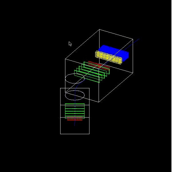
You may set invisibility to some logical volumes.